

 الفيزياء الكلاسيكية
 الكهربائية والمغناطيسية
 علم البصريات
 الفيزياء الحديثة
 النظرية النسبية
 الفيزياء النووية
 فيزياء الحالة الصلبة
 الليزر
 علم الفلك
 المجموعة الشمسية
 الطاقة البديلة
 الفيزياء والعلوم الأخرى
 مواضيع عامة في الفيزياء
|
Read More
Date: 16-2-2017
Date: 9-1-2017
Date: 22-12-2020
|
THE RC CIRCUIT
The capacitor circuits we have discussed so far are not too exciting. When you are working with an electronic circuit you do not hitch capacitors together in series or parallel, you simply go to the parts drawer and select a capacitor of the desired value.
If we add a resistor to the circuit as shown in Figure (1), we begin to get some interesting results. The circuit is designed so that if the mercury switch is closed, the capacitor is charged up to a voltage Vb by the battery. Then, at a time we will call t = 0, the switch is opened, so that the capacitor will discharge through the resistor. During the discharge, the battery is disconnected and the only part of the circuit that is active is that shown in Figure (2). (The reason for using a mercury switch was to get a clean break in the current. Mechanical switches do not work well.)

Figure 1: An RC circuit. When the mercury switch is closed, the capacitor quickly charges up to a voltage VC = Vb . When the switch is opened, the capacitor discharges through the resistor.

Figure 2: Capacitor discharge. When the switch is open, the only part of the circuit we have to look at is the capacitor discharging through the resistor.
Figure (3) shows the capacitor voltage just before and for a while after the switch was opened. We are looking at the experimental results of discharging a C = 10-6 farad (one microfarad) capacitor through an R = 104 ohm resistor. We see that a good fraction of the capacitor voltage has decayed in about 10 milliseconds (10-2 seconds) .

Figure 3: Experimental results from discharging the one microfarad 10 – 6 f capacitor through a 10 k ohm 104Ω resistor. The switch, shown in Figure 2, is thrown at time t = 0.
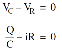
To analyze the capacitor discharge, we apply Kirchoff’s law to the circuit in Figure (2). Setting the sum of the voltage rises around the circuit equal to zero gives

which can be written in the form
 ........(1)
The problem with Equation (1) is that we have two unknowns, i and Q, and only one equation. We need to find another relationship between these variables in order to predict the behavior of the circuit.
The additional relationship is obtained by noting that the current i is the number of coulombs per second flowing out of the capacitor. In a short time dt, an amount of charge dQ that leaves the capacitor is given by
dQ = idt .......(2)
Dividing Equation (2) through by dt, and including a minus sign to represent the fact that i is causing a decrease in the charge Q in the capacitor, we get
 ..........(3)
Substituting Equation (3) in (1) gives one equation for the unknown Q
 ..........(4)


|
|
|
|
هل يمكن أن تكون الطماطم مفتاح الوقاية من السرطان؟
|
|
|
|
|
|
|
اكتشاف عرائس"غريبة" عمرها 2400 عام على قمة هرم بالسلفادور
|
|
|
|
|
|
|
جامعة الكفيل تقيم ندوة علمية عن الاعتماد الأكاديمي في جامعة جابر بن حيّان
|
|
|