

 الفيزياء الكلاسيكية
 الكهربائية والمغناطيسية
 علم البصريات
 الفيزياء الحديثة
 النظرية النسبية
 الفيزياء النووية
 فيزياء الحالة الصلبة
 الليزر
 علم الفلك
 المجموعة الشمسية
 الطاقة البديلة
 الفيزياء والعلوم الأخرى
 مواضيع عامة في الفيزياء
|
أقرأ أيضاً
التاريخ: 2024-03-18
التاريخ: 2024-04-06
التاريخ: 20-3-2016
التاريخ: 21-3-2016
|
No one has ever been able to define the difference between interference and diffraction satisfactorily. It is just a question of usage, and there is no specific, important physical difference between them. The best we can do, roughly speaking, is to say that when there are only a few sources, say two, interfering, then the result is usually called interference, but if there is a large number of them, it seems that the word diffraction is more often used.
Thus we shall now discuss the situation where there are n equally spaced oscillators, all of equal amplitude but different from one another in phase, either because they are driven differently in phase, or because we are looking at them at an angle such that there is a difference in time delay. For one reason or another, we have to add something like this:

where ϕ is the phase difference between one oscillator and the next one, as seen in a particular direction. Specifically, ϕ=α+2πd sin θ/λ. Now we must add all the terms together. We shall do this geometrically. The first one is of length A, and it has zero phase. The next is also of length A and it has a phase equal to ϕ. The next one is again of length A and it has a phase equal to 2ϕ, and so on. So we are evidently going around an equiangular polygon with n sides (Fig. 30–1).

Fig. 30–1.The resultant amplitude of n=6 equally spaced sources with net successive phase differences ϕ.
Now the vertices, of course, all lie on a circle, and we can find the net amplitude most easily if we find the radius of that circle. Suppose that Q is the center of the circle. Then we know that the angle OQS is just a phase angle ϕ. (This is because the radius QS bears the same geometrical relation to A2 as QO bears to A1, so they form an angle ϕ between them.) Therefore, the radius r must be such that A=2r sin ϕ/2, which fixes r. But the large angle OQT is equal to nϕ, and we thus find that AR=2r sin nϕ/2. Combining these two results to eliminate r, we get

Now let us analyze this expression and study some of its consequences. In the first place, we can check it for n=1. It checks: I=I0. Next, we check it for n=2: writing sin ϕ=2 sin ϕ/2 cos ϕ/2, we find that AR=2A cos ϕ/2, which agrees with (29.12).

Now the idea that led us to consider the addition of several sources was that we might get a much stronger intensity in one direction than in another; that the nearby maxima which would have been present if there were only two sources will have gone down in strength. In order to see this effect, we plot the curve that comes from (30.3), taking n to be enormously large and plotting the region near ϕ=0. In the first place, if ϕ is exactly 0, we have 0/0, but if ϕ is infinitesimal, the ratio of the two sines squared is simply n2, since the sine and the angle are approximately equal. Thus, the intensity of the maximum of the curve is equal to n2 times the intensity of one oscillator. That is easy to see, because if they are all in phase, then the little vectors have no relative angle and all n of them add up so the amplitude is n times, and the intensity n2 times, stronger.
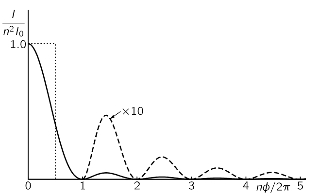
As the phase ϕ increases, the ratio of the two sines begins to fall off, and the first time it reaches zero is when nϕ/2=π, because sin π=0. In other words, ϕ=2π/n corresponds to the first minimum in the curve (Fig. 30–2). In terms of what is happening with the arrows in Fig. 30–1, the first minimum occurs when all the arrows come back to the starting point; that means that the total accumulated angle in all the arrows, the total phase difference between the first and last oscillator, must be 2π to complete the circle.

Fig. 30–2. The intensity as a function of phase angle for a large number of oscillators of equal strength.
Now we go to the next maximum, and we want to see that it is really much smaller than the first one, as we had hoped. We shall not go precisely to the maximum position, because both the numerator and the denominator of (30.3) are variant, but sin ϕ/2 varies quite slowly compared with sin nϕ/2 when n is large, so when sin2 nϕ/2=1 we are very close to the maximum. The next maximum of sin2 nϕ/2 comes at nϕ/2=3π/2, or ϕ=3π/n. This corresponds to the arrows having traversed the circle one and a half times. On putting ϕ=3π/n into the formula to find the size of the maximum, we find that sin2 3π/2=1 in the numerator (because that is why we picked this angle), and in the denominator we have sin2 3π/2n. Now if n is sufficiently large, then this angle is very small and the sine is equal to the angle; so, for all practical purposes, we can put sin 3π/2n=3π/2n. Thus, we find that the intensity at this maximum is I=I0(4n2/9π2). But n2I0 was the maximum intensity, and so we have 4/9π2 times the maximum intensity, which is about 0.045, less than 5 percent, of the maximum intensity! Of course, there are decreasing intensities farther out. So, we have a very sharp central maximum with very weak subsidiary maxima on the sides.
It is possible to prove that the area of the whole curve, including all the little bumps, is equal to 2πnI0, or twice the area of the dotted rectangle in Fig. 30–2.

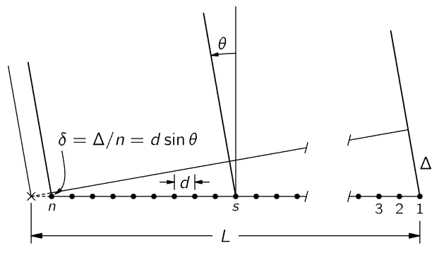
Fig. 30–3. A linear array of n equal oscillators, driven with phases αs=sα.
Now let us consider further how we may apply Eq. (30.3) in different circumstances, and try to understand what is happening. Let us consider our sources to be all on a line, as drawn in Fig. 30–3. There are n of them, all spaced by a distance d, and we shall suppose that the intrinsic relative phase, one to the next, is α. Then if we are observing in a given direction θ from the normal, there is an additional phase 2πd sin θ/λ because of the time delay between each successive two, which we talked about before. Thus

First, we shall take the case α=0. That is, all oscillators are in phase, and we want to know what the intensity is as a function of the angle θ. In order to find out, we merely have to put ϕ=kd sinθ into formula (30.3) and see what happens. In the first place, there is a maximum when ϕ=0. That means that when all the oscillators are in phase there is a strong intensity in the direction θ=0. On the other hand, an interesting question is, where is the first minimum? That occurs when ϕ=2π/n. In other words, when 2πd sin θ/λ=2π/n, we get the first minimum of the curve. If we get rid of the 2π’s so we can look at it a little better, it says that

Now let us understand physically why we get a minimum at that position. nd is the total length L of the array. Referring to Fig. 30–3, we see that nd sin θ=L sin θ=Δ. What (30.5) says is that when Δ is equal to one wavelength, we get a minimum. Now why do we get a minimum when Δ=λ? Because the contributions of the various oscillators are then uniformly distributed in phase from 0∘ to 360∘. The arrows (Fig. 30–1) are going around a whole circle—we are adding equal vectors in all directions, and such a sum is zero. So when we have an angle such that Δ=λ, we get a minimum. That is the first minimum.
There is another important feature about formula (30.3), which is that if the angle ϕ is increased by any multiple of 2π, it makes no difference to the formula. So we will get other strong maxima at ϕ=2π, 4π, 6π, and so forth. Near each of these great maxima the pattern of Fig. 30–2 is repeated. We may ask ourselves, what is the geometrical circumstance that leads to these other great maxima? The condition is that ϕ=2πm, where m is any integer. That is, 2πd sin θ/λ=2πm. Dividing by 2π, we see that

This looks like the other formula, (30.5). No, that formula was nd sin θ=λ. The difference is that here we have to look at the individual sources, and when we say d sin θ=mλ, that means that we have an angle θ such that δ=mλ. In other words, each source is now contributing a certain amount, and successive ones are out of phase by a whole multiple of 360∘, and therefore are contributing in phase, because out of phase by 360∘ is the same as being in phase. So, they all contribute in phase and produce just as good a maximum as the one for m=0 that we discussed before. The subsidiary bumps, the whole shape of the pattern, is just like the one near ϕ=0, with exactly the same minima on each side, etc. Thus, such an array will send beams in various directions—each beam having a strong central maximum and a certain number of weak “side lobes.” The various strong beams are referred to as the zero-order beam, the first-order beam, etc., according to the value of m. m is called the order of the beam.
We call attention to the fact that if d is less than λ, Eq. (30.6) can have no solution except m=0, so that if the spacing is too small there is only one possible beam, the zero-order one centered at θ=0. (Of course, there is also a beam in the opposite direction.) In order to get subsidiary great maxima, we must have the spacing d of the array greater than one wavelength.


|
|
|
|
5 علامات تحذيرية قد تدل على "مشكل خطير" في الكبد
|
|
|
|
|
|
|
اللجنتان العلمية والتحضيرية تناقش ملخصات الأبحاث المقدمة لمؤتمر العميد العالمي السابع
|
|
|