آخر المواضيع المضافة

 الفيزياء الكلاسيكية
الكهربائية والمغناطيسية
علم البصريات
الفيزياء الحديثة
النظرية النسبية
الفيزياء النووية
فيزياء الحالة الصلبة
الليزر
علم الفلك
المجموعة الشمسية
الطاقة البديلة
الفيزياء والعلوم الأخرى
مواضيع عامة في الفيزياء
الفيزياء الكلاسيكية
الكهربائية والمغناطيسية
علم البصريات
الفيزياء الحديثة
النظرية النسبية
الفيزياء النووية
فيزياء الحالة الصلبة
الليزر
علم الفلك
المجموعة الشمسية
الطاقة البديلة
الفيزياء والعلوم الأخرى
مواضيع عامة في الفيزياء| The Hartley circuit |


|
|
Read More
Date: 2-5-2021
Date: 29-4-2021
Date: 30-4-2021
|
The Hartley circuit
A method of obtaining controlled feedback at RF is shown in Fig. 1. At A, an NPN bipolar transistor is used; at B, an N-channel JFET is employed. The PNP and P-channel circuits are identical, but the power supply is negative instead of positive.
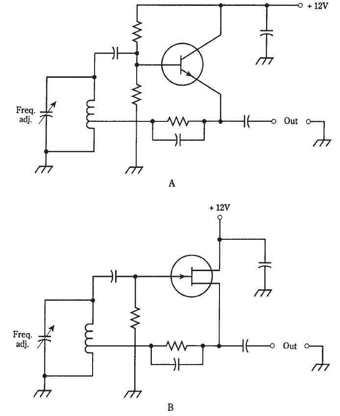
Fig. 1: Hartley oscillators. At A, NPN bipolar transistor; at B, N-channel JFET.
The circuit uses a single coil with a tap on the windings to provide the feedback. A variable capacitor in parallel with the coil determines the oscillating frequency, and allows for frequency adjustment. This circuit is called a Hartley oscillator.
The Hartley oscillator uses about one-quarter of its amplifier power to produce feedback. (Remember, all oscillators are really specialized amplifiers.) The other three-quarters of the power can be used as output. Oscillators do not, in general, produce more than a fraction of a watt of power. If more power is needed, the signal can be boosted by one or more stages of amplification. It’s important to use only the minimum amount of feedback necessary to get oscillation. The amount of feedback is controlled by the position of the coil tap.


|
|
|
|
كيف تعزز نمو الشعر الصحي؟
|
|
|
|
|
|
|
10 فحوصات مهمة يجب القيام بها لسيارتك قبل الصيف
|
|
|
|
|
|
جامعة الزهراء (عليها السلام) تكرم قسم الشؤون الفكرية بمناسبة اليوم العالمي للكتاب
|
|
|
|
قسم شؤون المعارف يقيم ندوة علمية حول جهود علماء البصرة في نشر الحديث
|
|
|
|
قسم الشؤون الفكرية يختتم برنامجاً ثقافياً لوفدٍ من جامعة البصرة
|
|
|
|
جامعة الكفيل تعقد ورشة عمل عن إجراءات عمل اللجان الامتحانيّة
|