This final section on relay circuits contains two examples in which the sequence diagram is not given but the situation calls for the construction of a sequence diagram as part of the solution to the problem. This situation is more realistic than those of Section (Design of sequential relay circuits from given conditions) and corresponds closely to the problem which faces the designer in practical applications of the techniques we have presented.
Suppose that it is desired to obtain four or more signals from two keys in such a way that no signal is given when both keys are in released position. Combinational circuits alone will not solve the problem since there are only four states possible for two switches and one of these (both released) is specifically excluded. Sequential signals, using secondary relays, must therefore be used. The problem is made more specific in the following example.
EXAMPLE 1. Design a sequential circuit to cause four lights, red, white, blue, and green, respectively, to flash individually.
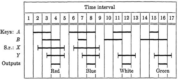
FIG. 1-1. Sequence diagram for four signals from two keys.
Solution. Many sequential inputs could be chosen, but those of Fig. 5-38 are a reasonable choice. The input combinations based on keys A and B are simple enough to be easily learned, but complex enough to make control of secondary relays easy. The four sequences are the signals in time intervals 2-4, 6-8, 10-12, and 14-16, respectively. An interval in which both keys are released is shown between each sequence since we will permit the sequences to occur in an arbitrary order. Because of this, it is necessary to cause all secondary relays, as well, to release in intervals 5, 9, 13, and 17. A suitable sequence of operation is shown for secondary relays X and Y which will distinguish between the four signals. The red light will be controlled by an output in 4, the blue light by anoutput in 8, the white light by an output in 12, and the green light by an output in 16. The output functions are Fr = a'bzy, Fw = ab'xy, Fb = ab'x'y, and Fg = a'bx'y. The control functions for relays X and F are Fz = ab'y' - (a + b)x and Fy = ab + (a + b)y. The corresponding circuit is left to the reader.
EXAMPLE 2. An electric combination lock is to be designed based on five visible keys A, B, C, D, and E and too hidden keys F and G. A solenoid is to withdraw the bolt when keys B E A D are pressed consecutively, in that order only. (The solenoid is operated by current through its winding.) A burglar alarm is to sound if any error is made in manipulation of the keys. Key F is to shut off the alarm and release all secondary relays. Key G is to reset the lock.
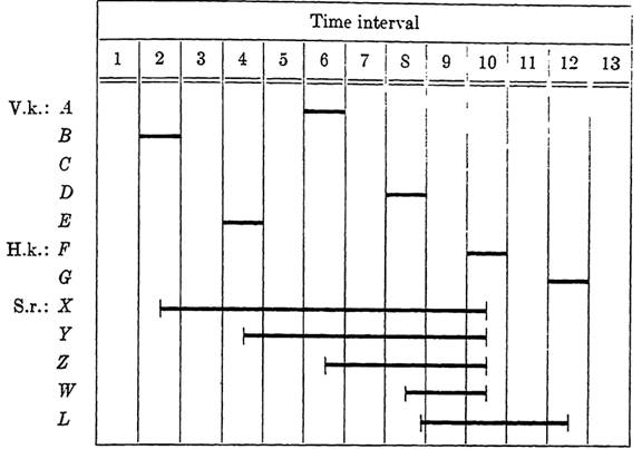
FIG. 1-2. Sequence diagram for the combination lock of Example 2. V.k. and H. k. denote visible and hidden keys.
Solution. First we will arrange two relays, T to operate the alarm, and L to operate the solenoid which releases the lock. This is done through make contacts on the relays. The reason for using relays here is that they permit locking paths to be introduced to maintain operation until the appropriate key is depressed to cause release of these devices. Figure 5-39 shows the correct operating sequence for operation of L and all secondary relays needed, except the one used to control the alarm. The latter cannot be shown without drawing all incorrect sequences as well.
The control functions are then given by
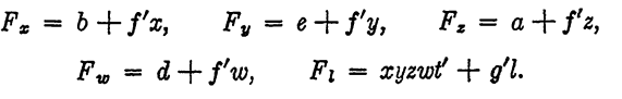
Here the t' in the control function for L guarantees that the lock bolt will never be withdrawn if the alarm is sounding. Finally, the alarm relay T is controlled by
Ft= c+x'y+ y'z+z'w+f't.
Note that the alarm will ring in case an error of any type is made. From these functions, the circuit can be readily drawn. This is left to the reader.


