One very important operation that can be performed on a calculator is that of accumulation. Accumulation is nothing more than repeated addition (or subtraction). Instead of receiving two numbers as inputs and producing a third as an output, the accumulator accepts numbers one at a time. As each number is received, the accumulator adds it to the number already stored and then stores the sum. In the process, the original numbers are erased and only the sum remains. Because of the necessity for storing a number, then changing it to a new number which is again stored, it is reasonably obvious that the flip-flop will be a basic element in an accumulator.
The accumulator register will be a sequence of flip-flops, one of which will correspond to each digit of the number stored. This register will have a number stored in it at the beginning of the operation we are considering. (This could, of course, be the number zero.) The addend, which is to be added to the number stored in the accumulator, will be a number stored on a second sequence of flip-flops constituting the addend register. We will design an accumulator in units by thinking separately of each part of the circuit which involves a given digit only, say the nth digit, of the numbers involved. This part of the circuit, or unit, will be repeated for each digit, with the exception of the first and last digits, where minor modifications are required.
The function of the nth unit of the accumulator is represented in Table 1-1. The inputs for this unit consist of the signals from the accumulator register, addend register, and the carry from the preceding unit. The outputs consist of a carry to the next higher position and, for convenience, the complement of this carry, which we will call noncarry and designate by n or c', and finally a pulse which may or may not be applied to the accumulator. When necessary, this pulse changes the state of the accumulator digit to represent the new sum, which will be stored following the addition operation. The inputs and outputs of this unit are shown schematically in Fig. 1-1.
The major difficulty is that this cannot be a combinational circuit. The nature of the flip-flop in the accumulator makes it necessary for the circuit to be sequential. It will be convenient, circuitwise, to perform the computations for carry before that for sum. The reason is that the carry output
TABLE 1-1
FUNCTION OF AN ACCUMULATOR UNIT
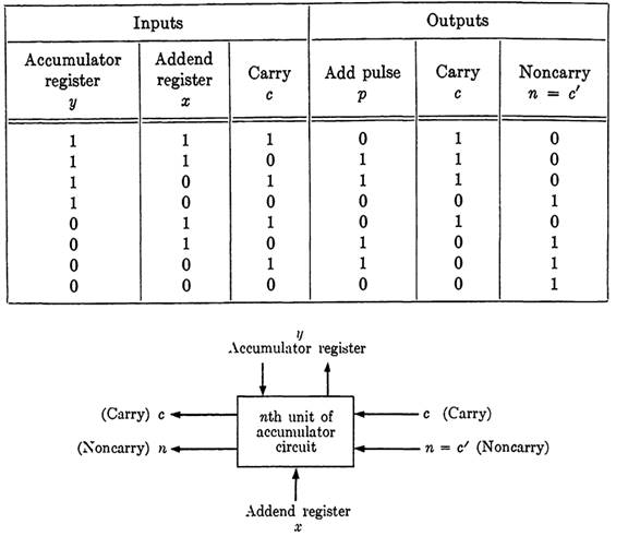
FICA. 1-1. Block diagram of an accumulator unit.
depends on the carry input, the addend register, and the accumulator register as it was before the addition. If the pulse to the accumulator were supplied before the carry output is established, an erroneous result would be obtained. The method which we will use (and this is only one of many) is carried out in the following steps.
1. Addend is supplied to addend register.
2. Signal is supplied to noncarry input of the lowest-order digit.
3. After all carry outputs are stable, an "add pulse" is supplied simultaneously to each unit.
Step 1 is self-explanatory, and merely supplies the required addend inputs as steady signals. Now a signal is applied to noncarry at the lowest order to start the propagation of carry signals throughout the circuit. The circuit should be such that each unit in turn, from lowest to highest order,
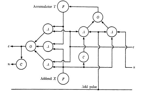
FIG. 1-2. Logical circuit for the nth unit of a binary accumulator.
will stabilize with proper carry-signal outputs. The circuit for the pulse to the accumulator must be such that nothing happens until all carry outputs have been formed. This is accomplished by supplying a pulse, termed an add pulse and designated p, to each unit after the carry signal has passed through all units. The proper timing can be determined from the carry signals, since they are paired so that one or the other will always produce a signal. When the carry reaches the highest-order unit, the add-pulse signal is given, causing the new sum to appear in the accumulator register.
From Table 1-1, the functions for the outputs of a unit can be readily computed as follows.
Output to accumulator: f = (x'c + xc')p. Here p is the add pulse mentioned in the preceding paragraph.
Carry output: c = xy + ye + xc. Here c on the left side of the equation refers to output carry, and on the right to input carry.
Noncarry output: n = (xy + yc + xc)'. Since this signal is the negative of the preceding, it can be obtained through a single "complement" element.
The logical circuit for the nth unit is shown in Fig. 1-3. This accumulator, or any of the many circuits which accomplish the same result, is of great value in a computer. In addition to its obvious use for summing sets of addends, it can be employed to advantage in many more complicated arithmetic operations, among them that of multiplication. In attempting to assess the relative merits of an accumulator as compared with an adder, other factors are so important that it is impossible to obtain any positive answer. The type of storage device available in the machine for use with the adder, the mechanism used for shifting the position of a number, etc., are all involved. An adder with a storing device is equivalent to an accumulator, although the sequence of operations is different. A computer could be constructed either with or without an accumulator as such.


