Figure 1-1 illustrates the most general kind of control circuit for the operation of a singly wound relay X. It consists of two circuits, the first of which we will refer to as the operate path. This is the circuit which represents the conditions for which it is desired that the relay will operate initially. In the figure, this circuit is shown as a single letter A, which may correspond to a single contact or to a complicated circuit. The second circuit controlling the operation of the relay X, which we will refer to as the hold path, represents those conditions for which it is desired that the relay will remain in operation after once being operated. This circuit will always contain a make contact on relay X and may contain a circuit in series with this contact, designated by the single letter B in the figure.
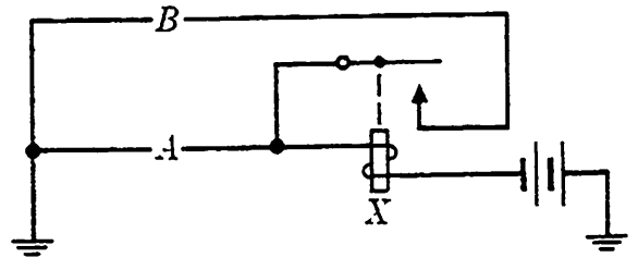
FIG. 1-1. General operate and hold paths for a relay X.
Normally, the conditions for which the relay is to operate and those for which it is to hold are given separately, and the circuit design is begun by considering the corresponding functions separately. After initial simplifications of operate and hold paths have been performed, it may be possible to effect combinations of these paths in such a way as to lead to further simplifications, as we will see presently. From Fig. 1-1, it is apparent that the function F representing the conditions controlling relay X may be written as F = f∘+ xfh,, where f,, is the function representing the operate path A and fh is the function representing the hold path B.
EXAMPLE 1. A relay X is to be controlled in the following way from inputs A, B, C, D, and E.
X is to operate initially if and only if one or more of the following conditions are satisfied:
(a) B, D, and E are operated; A and C are released,
(b) B, C, D, and E are operated; .1 is released,
(c) B, C, and B are operated; A and D are released,
(cl) B and B are operated; A, C, and D are released,
(e) C and E are operated; .1, B, and D are released,
(f) A, C, and B are operated; D and B are released,
(g) A, B, C, and E are operated; D is released.
In addition, X is to remain operated if one or more of the following conditions are satisfied. [Note that the relay will hold for all operate conditions as well.
Hence duplication of (a) through (g) is unnecessary.]
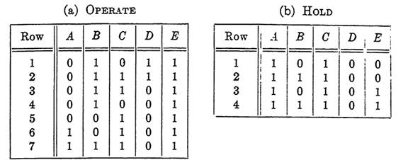
Tables. 1-1.
(h) A and C are operated; B, D, and E are released,
(i) A, B, and C are operated; D and E are released.
It is awkward to visualize all these conditions at once, but if we use a table to represent the conditions, they are much easier to work with. Tables 1-1(a) and (b) are of the same type as those in Sections (Design of circuits from given properties) and (Design of n-terminal circuits) except that the only rows shown are those corresponding to the combinations for which the function assumes the value 1. All other combinations correspond to the value 0 for the function. Since the inputs will be interpreted as controlling relays, the symbols 0 and 1 refer to the states of relays, a slight extension of the earlier interpretations. 1 will signify that the relay is in the operated state, 0 that it is in the released state.
The first two rows of Table 1-1(b) represent the given hold conditions. The last two rows are duplications of rows 6 and 7 of Table (a), representing operate conditions, which are included in Table (b) to aid in simplifying the corresponding function. We are assuming, in this section, that all input relays operate instantaneously so that during a change of state from one combination to another of the given conditions, the relay being controlled will not release.
To determine fo, we note that rows 1, 2, 3, and 4 of Table 1-1(a) are alike except for columns C and D. Similarly, rows 3, 5, 6, and 7 are alike except for columns A and B. The correct function is f0 = a'be + cd'e = (a'b + cd')e. Here row 3 was used twice to make the resulting function as simple as possible. The law of tautology for Boolean algebra justifies this. It is necessary to use each row at least once, but any row may be used as often as desired. To determine fh, we note that in Table 1-1(b), rows 1, 2, 3, and 4 are alike except for columns B and E. The correct function is therefore fh = acd'. The control function for relay X may then be written as F = (a'b + cd')e + xacd'. If we add the zero term xaa'b, we may factor F as follows:
F = (a'b + cd) (e + xa).
The circuit diagram is given in Fig. 1-2, making use of the factor that is common to the operate and hold paths, as shown above. The methods and examples of Section (n-terminal circuits and the uses of transfer contacts) apply here as well as to circuits that control separate relays.
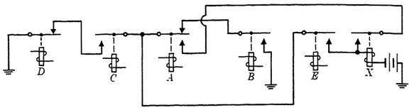
FIG. 1-2. Control circuit of Example 1.
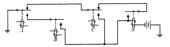
FIG. 1-3. Control circuit of Example 2.
EXAMPLE 2. If we suppose that the function representing the control circuit for a relay is F = ab + a'c + x(a'c'), then the circuit may be drawn as in Fig. 1-3, where the break contact on A is common to the hold and operate paths, and a transfer contact on C is used to ensure that the paths are disjunctive.


