
آخر المواضيع المضافة

 الفيزياء الكلاسيكية
الكهربائية والمغناطيسية
علم البصريات
الفيزياء الحديثة
النظرية النسبية
الفيزياء النووية
فيزياء الحالة الصلبة
الليزر
علم الفلك
المجموعة الشمسية
الطاقة البديلة
الفيزياء والعلوم الأخرى
مواضيع عامة في الفيزياء
الفيزياء الكلاسيكية
الكهربائية والمغناطيسية
علم البصريات
الفيزياء الحديثة
النظرية النسبية
الفيزياء النووية
فيزياء الحالة الصلبة
الليزر
علم الفلك
المجموعة الشمسية
الطاقة البديلة
الفيزياء والعلوم الأخرى
مواضيع عامة في الفيزياء| ACOUSTOOPTIC MODULATORS |


|
|
Read More
Date: 8-1-2021
Date: 2-1-2021
Date: 21-3-2016
|
ACOUSTOOPTIC MODULATORS
Perhaps the simplest (and most common) modulator is the acoustooptic modulator. An acoustic wave, at radio frequencies, originates from a piezoelectric crystal which

Figure 1.1. Acoustooptic modulator.
generates a surface acoustic wave in a crystal as outlined in Figure 1.1. The waves generated by the piezoelectric crystal form almost entirely flat plane wave fronts in the crystal. This wave is transmitted through a quartz crystal and induces a strain in the crystal which changes its refractive index on a localized scale. Like a sound wave propogating through air, the acoustic wave creates rarefactions and compressions that change the density of the crystal. This is a photoelastic effect in which the strain distorts bonds between atoms of the crystal. The end of the crystal is either cut at an angle or terminated with an acoustic absorber so that a standing wave is not generated in the crystal. The acoustic wave, although at radio frequencies, propagates through the crystal at the speed of sound, so the wavelength of the acoustic wave inside the crystal is
 (1.1)
(1.1)
where Λ is the wavelength inside the crystal and f is the frequency. Thus, we have a relatively long wavelength in the crystal. Regions of high and low index of refraction will similarly exist in the crystal at these points, as outlined on Figure 1.2.
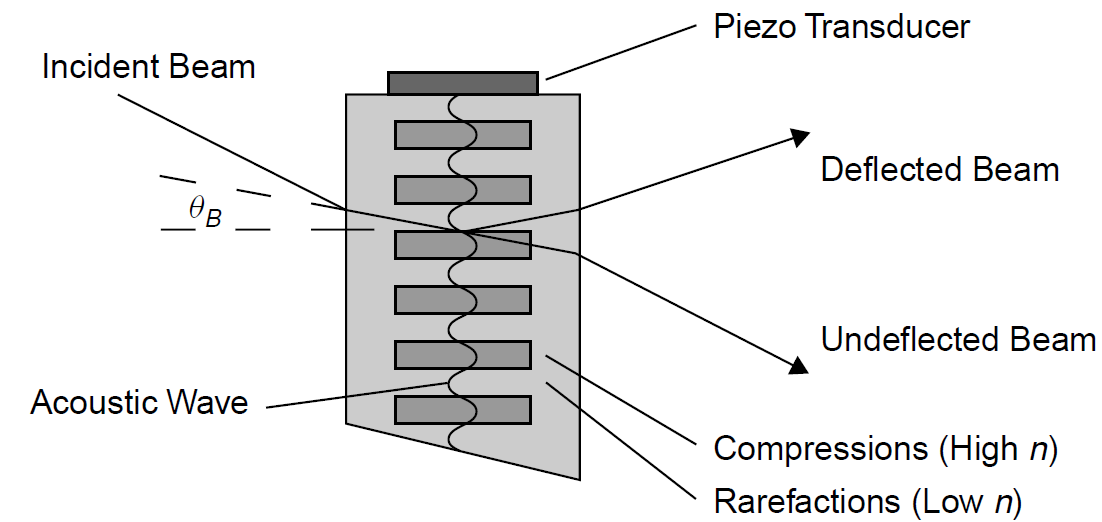
Figure 1.2. Acoustic waves in an AO modulator (Bragg diffraction condition).
Because these layers of varying n are stacked together, diffraction will occur and an incoming beam of light will change deflection upon passing through the crystal. Two types of diffraction may occur here, Bragg diffraction and Raman–Nath diffraction, depending on the angle of incidence of the beam to be diffracted.
In the Bragg regime, a light beam is deflected by the alternating layers of differing refractive indices. Bragg diffraction refers to a type of diffraction generated when x-rays are incident on crystals. The very short wavelengths of x-rays rule out using diffraction gratings constructed using parallel lines ruled in, for example, glass. X-ray wavelengths, however, correspond to the spacings of atoms in crystal lattices, so crystals may be used as three-dimensional diffraction gratings. In 1912, W. L. Bragg discovered that the structure of a crystal is repetitive in three dimensions, with atoms aligned in parallel planes on each of which the arrangement of atoms is the same. These parallel planes are called Bragg planes. Incident x-rays are reflected from such a crystal (actually diffracted) according to a simple law by Bragg.
In the case of an AO modulator, the acoustic wave inside a crystal sets up parallel planes of varying indexes of refraction, which like the parallel planes of atoms in the crystal, generate Bragg diffraction of an incident light beam. The wavelength of the acoustic wave in the crystal corresponds to the wavelength of the incident light beam just as the spacing of the atoms in the crystal corresponds to x-ray wavelengths. An incident light beam on an AO modulator crystal is deflected only when an acoustic wave is present in the crystal (i.e., it is driven by a radio-frequency (RF) source). Mathematically, this deflection can be expressed in a manner similar to that for an optical diffraction grating:
 (1.2)
(1.2)
where θB is the Bragg angle and λ is the wavelength in air. When this equation is satisfied, reflected waves from each parallel plane will be separated by a phase shift of exactly 2π, so that constructive interference takes place. The exit beam is deflected out of the crystal at the same angle as it enters, shown in Figure 1.2 as the deflected beam. As well as being useful as a modulator (by deflecting the intracavity beam out of the cavity, hence preventing amplification when the modulator is on), this type of diffraction may be used to deflect a beam and hence may be used as a beam scanner.
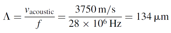
Example 1.1 Calculation of the Angle of Deflection Consider an AO modulator driven with a 28-MHz signal and made of quartz used to deflect the beam of a HeNe laser. The speed of sound in quartz is 3750 m/s and quartz has an index of refraction of 1.46. Calculate the angle of deflection caused by this modulator when used in the Bragg regime.
SOLUTION The wavelength of the acoustic wave in the quartz crystal is
The angle of deflection may now be found as
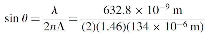
The angle is hence found to be 0.093 degree. The modulator is placed within the laser cavity so that radiation within the laser cavity is incident on the plane waves at this angle. When the modulator is off, light passes through unimpeded; when on, light is deflected out of the cavity, spoiling the resonance (Q) of the laser cavity.
It must be noted that the angle of diffraction does not depend on the intensity of the acoustic wave: Increasing this parameter (by increasing the RF drive signal) simply changes the intensity of the diffracted light beam. Of course, there are physical limits on how much energy a given switch will tolerate.
The second type of diffraction, Raman–Nath diffraction, occurs when the incoming beam is aligned perpendicular to the alternating layers, which now act like parallel slits in a transmission diffraction grating. In this regime the diffraction is modeled to occur from a thin acoustic wave beam inside the crystal. The angle of diffraction is quite different from the Bragg angle and the incoming light beam is deflected in both directions (both upward and downward) away from the plane of
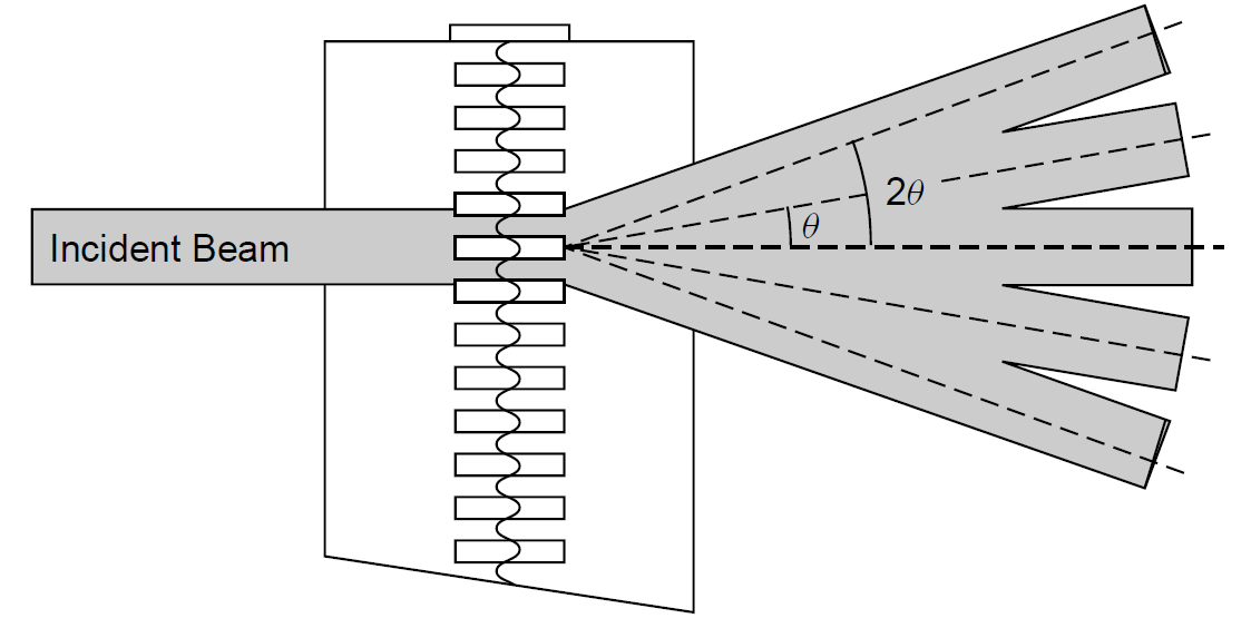
Figure 1.3. Raman–Nath diffraction from an AO modulator.
(a)

(b)
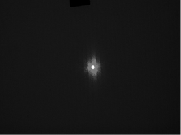
Figure 1.4. Diffraction with an AO modulator.
the incident light beam. Also, multiple high-order diffractions may occur as in Figure 1.3.
It is diffraction that allows the AO modulator in this regime to act as a switch. When inserted inside a laser cavity, the diffraction caused by the AO Q-switch causes a portion (but not all) of the intracavity beam to be deflected away from the inside of the cavity so that it is not reflected into the laser medium for further amplification, thereby spoiling laser action. The Q of the cavity falls from its normal value to a much lower value as losses increase in the cavity due to the diffraction. A practical modulator (as employed in a YAG laser) is depicted in Figure 1.1. In a test setup a laser beam is passed through this modulator. The modulator requires an RF drive signal at a frequency of 27 to 28 MHz and a minimum power of 10 W. Most commercial Q-switches operate at frequencies of 24, 27, or 80 MHz with drive power levels of 5 to 50 W. In this test, whose results are shown in Figure 1.4, the output beam (having passed through the device) is observed with the RF drive signal turned on and off. The diffraction pattern showing a strong first-order and weak second-order components is clearly visible when the RF source is energized.
As evident in Figure 1.4, AO modulators used in this mode have low hold-off ratios. In the case of this modulator, the intensity of the central beam is of concern since it is this component that is amplified in the laser. In the test above, the modulator was observed to cause a 10% loss in the power of the central beam when energized. In Figure 1.4(b), the brightness of the central spot with the switch energized is still significant, so this switch is by no means absolute: The blocked state (with the RF supply on) still allows a reasonably large amount of light to pass unimpeded (EO modulators have much better extinction of light when energized). This is still quite suitable for use in low-gain lasers (with less than 10% net gain per pass) such as CW lamp-pumped YAG lasers, but not in higher-gain lasers, where a 10% loss will still allow lasing to occur. When operated in the Bragg regime, the same modulator shows a higher hold-off ratio(> 90%) but still not nearly as high as that of an EO modulator.
AO modulators are by far the most common for laser Q-switches. They are inexpensive (the crystal for most modulators is made of quartz), and the drive circuitry is a simple RF oscillator and power amplifier. With a suitable antireflective coating on the faces of the crystal (which is wavelength specific), the insertion loss is almost negligible, allowing it to be used with low-gain lasers.


|
|
|
|
دخلت غرفة فنسيت ماذا تريد من داخلها.. خبير يفسر الحالة
|
|
|
|
|
|
|
ثورة طبية.. ابتكار أصغر جهاز لتنظيم ضربات القلب في العالم
|
|
|
|
|
|
|
العتبة العباسية المقدسة تقدم دعوة إلى كلية مزايا الجامعة للمشاركة في حفل التخرج المركزي الخامس
|
|
|