تاريخ الفيزياء
علماء الفيزياء


الفيزياء الكلاسيكية
الميكانيك
الديناميكا الحرارية
الكهربائية والمغناطيسية
الكهربائية
المغناطيسية
الكهرومغناطيسية
علم البصريات
تاريخ علم البصريات
الضوء
مواضيع عامة في علم البصريات
الصوت
الفيزياء الحديثة
النظرية النسبية
النظرية النسبية الخاصة
النظرية النسبية العامة
مواضيع عامة في النظرية النسبية
ميكانيكا الكم
الفيزياء الذرية
الفيزياء الجزيئية
الفيزياء النووية
مواضيع عامة في الفيزياء النووية
النشاط الاشعاعي
فيزياء الحالة الصلبة
الموصلات
أشباه الموصلات
العوازل
مواضيع عامة في الفيزياء الصلبة
فيزياء الجوامد
الليزر
أنواع الليزر
بعض تطبيقات الليزر
مواضيع عامة في الليزر
علم الفلك
تاريخ وعلماء علم الفلك
الثقوب السوداء
المجموعة الشمسية
الشمس
كوكب عطارد
كوكب الزهرة
كوكب الأرض
كوكب المريخ
كوكب المشتري
كوكب زحل
كوكب أورانوس
كوكب نبتون
كوكب بلوتو
القمر
كواكب ومواضيع اخرى
مواضيع عامة في علم الفلك
النجوم
البلازما
الألكترونيات
خواص المادة
الطاقة البديلة
الطاقة الشمسية
مواضيع عامة في الطاقة البديلة
المد والجزر
فيزياء الجسيمات
الفيزياء والعلوم الأخرى
الفيزياء الكيميائية
الفيزياء الرياضية
الفيزياء الحيوية
الفيزياء والفلسفة
الفيزياء العامة
مواضيع عامة في الفيزياء
تجارب فيزيائية
مصطلحات وتعاريف فيزيائية
وحدات القياس الفيزيائية
طرائف الفيزياء
مواضيع اخرى

The potentiometer
 المؤلف:
Stan Gibilisco
المؤلف:
Stan Gibilisco
 المصدر:
Teach Yourself Electricity and Electronics
المصدر:
Teach Yourself Electricity and Electronics
 الجزء والصفحة:
106
الجزء والصفحة:
106
 13-4-2021
 3411
3411


+
-
20
The potentiometer
All of the resistors mentioned are fixed in value. It is impossible to change or adjust their resistances. Of course, their values will change if they overheat, or if you chip pieces of them out, but they’re meant to provide an unchanging opposition to the flow of electric current.
It might have occurred to you that a variable resistor can be made by hooking up a bunch of fixed resistors in series or parallel, and then switching more or fewer of them in and out. This is almost never done in electronic circuits because there’s a better way to get a variable resistance: use a potentiometer.
The construction of a potentiometer is shown in simplified form in Fig. 1. A resistive strip is bent into a nearly complete circle, and terminals are connected to either end. This forms a fixed resistance. To obtain the variable resistance, a sliding contact is attached to a rotatable shaft and bearing, and is connected to a third terminal. The resistance between this middle terminal, and either of the end terminals, can vary from zero up to the resistance of the whole strip.
Some potentiometers use a straight strip of resistive material, and the control moves up and down, or from side to side. This type of variable resistor, called a slide potentiometer, is used in graphic equalizers, as the volume controls in some stereo amplifiers, and in some other applications when a linear scale is preferable to a circular scale. Potentiometers are made to handle only very low levels of current, at low voltage.
Linear taper
One type of potentiometer uses a strip of resistive material whose density is constant all the way around. This results in a linear taper. The resistance between the center terminal and either end terminal changes at a steady rate as the control shaft is turned.
Suppose a linear taper potentiometer has a value of zero to 280 Ω. In most units the shaft rotates about 280 degrees, or a little more than three-quarters of a circle. Then the resistance between the center and one end terminal will increase right along with the number of degrees that the shaft is turned. The resistance between the center and the other end terminal will be equal to 280 minus the number of degrees the shaft is turned. Engineers say that the resistance is a linear function of the shaft position.
Linear taper potentiometers are commonly used in electronic test instruments and in various consumer electronic devices. A graph of resistance versus shaft displacement for a linear taper potentiometer is shown in Fig. 2.
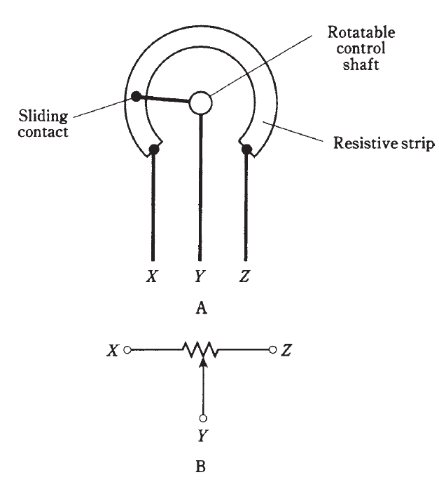
Fig. 1: At A, simplified drawing of the construction of a rotary potentiometer. At B, schematic symbol.
Audio or logarithmic taper
There are some applications for which linear taper potentiometers don’t work well. The volume control of a radio receiver is a good example. Your ear/brain perceives sound level according to the logarithm of its true level. If you use a linear taper potentiometer as the volume control of a transistor radio or other sound system, the level will seem to go up too slowly in some parts of the control range and too fast in other parts of the control range.
To compensate for the way in which people perceive sound level, an audio taper potentiometer is used. In this device, the resistance between the center and end terminal increases in a nonlinear way. This type of potentiometer is sometimes called a logarithmic-taper device.
If the shaft is all the way counterclockwise, the volume at the speaker is zero or near zero. If you turn the shaft 30 degrees clockwise, the volume increases to some perceived level; call it one sound unit. If you then turn the volume 30 degrees further clockwise, the volume will seem to go up to two sound units. But in fact it has increased much more than this, in terms of actual sound power.
You perceive sound not as a direct function of the true volume, but in units that are based on the logarithm of the intensity. Audio-taper potentiometers are manufactured so that as you turn the shaft, the sound seems to increase in a smooth, natural way. A graph of resistance versus shaft displacement for an audio-taper potentiometer is shown in Fig. 3.
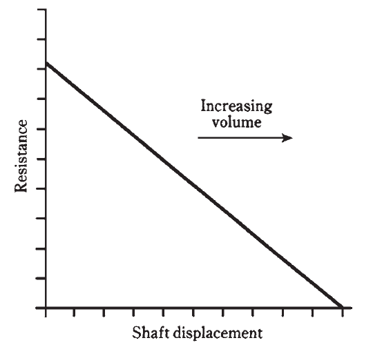
Fig. 2: Resistance-vs-displacement curve for linear taper potentiometer.
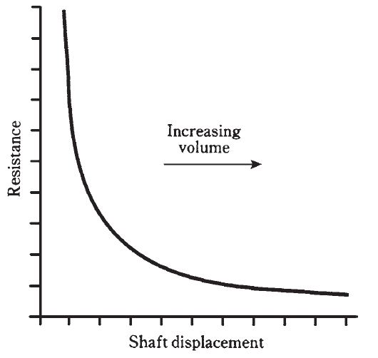
Fig. 3: Resistance-vs-displacement curve for audio-taper potentiometer.
 الاكثر قراءة في الألكترونيات
 اخر الاخبار
اخبار العتبة العباسية المقدسة

الآخبار الصحية


مواضيع ذات صلة
 قسم الشؤون الفكرية يصدر كتاباً يوثق تاريخ السدانة في العتبة العباسية المقدسة
 "المهمة".. إصدار قصصي يوثّق القصص الفائزة في مسابقة فتوى الدفاع المقدسة للقصة القصيرة
 (نوافذ).. إصدار أدبي يوثق القصص الفائزة في مسابقة الإمام العسكري (عليه السلام)