Parallel resonance
Refer to the circuit diagram of Fig. 1. This is a parallel RLC circuit. You remember that, in this case, the resistance R is thought of as a conductance G, with G�1/R. Then the circuit can be called a GLC circuit.
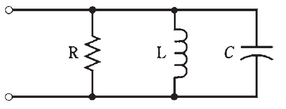
Fig. 1: A parallel RLC circuit.
At some particular frequency fo, the inductive susceptance BL will exactly cancel the capacitive susceptance BC; that is, BL = −BC. This is inevitable for some frequency fo, as long as the circuit contains finite, nonzero inductance and finite, nonzero capacitance. At the frequency fo, the susceptances cancel each other out, leaving zero susceptance.
The admittance through the circuit is then very nearly equal to the conductance, G, of the resistor. If the circuit contains no resistor, but only a coil and capacitor, it is called a parallel LC circuit, and the admittance at resonance will be extremely low.
The circuit will offer great opposition to alternating current at fo. Engineers think more often in terms of impedance than in terms of admittance; low admittance translates into high impedance. This condition is parallel resonance.


